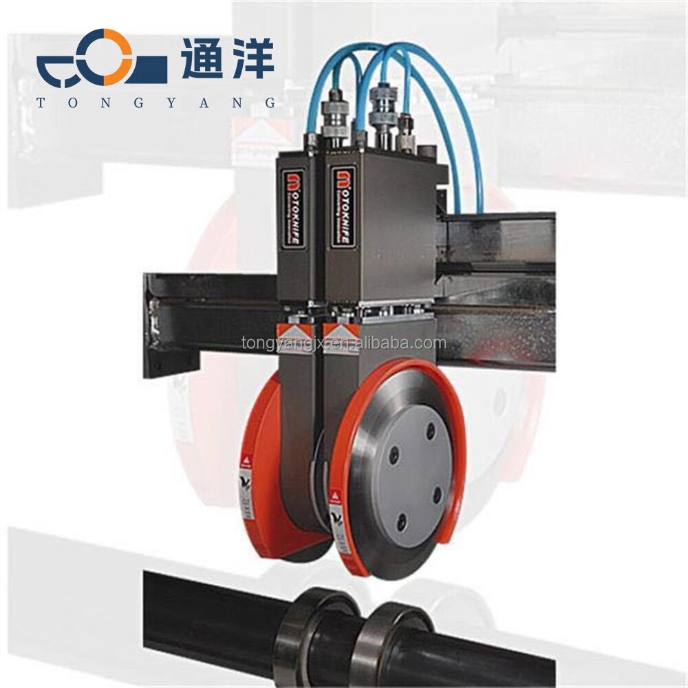
How to Install a Pneumatic Tool Holder and Ensure Its Working Accuracy
Preparation Before Installation
Thoroughly remove burrs, oil stains and metal chips from the machine tool saddle/mounting surface; wipe with alcohol or cleaning agent to ensure flatness within 0.02 mm.
Check the tool holder body, cutter disc, air cylinder, locking screws and locating pins for bumps, deformation and corrosion. Match the torque according to the bolt specifications.
Body Installation (Fixing and Precision)
Positioning and LevelingAttach the tool holder base tightly to the machine reference surface and locate it with positioning pins (to prevent rotation).Use a dial indicator to measure the end face runout and parallelism of the base, with an error ≤ 0.01 mm.
Locking bolts (crosswise and step-by-step tightening)
Tighten in diagonal sequence in 3 steps.
Reference torque:M8 ≈ 39 Nm, M10 ≈ 77 Nm, M12 ≈ 135 Nm
Do not tighten on one side or over-tighten (may cause deformation and seizing).
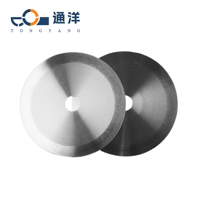
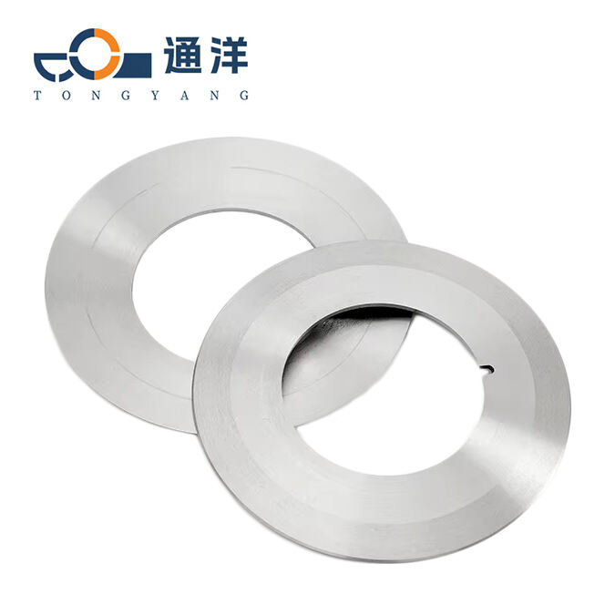
Cutter Disc InstallationClean the conical surface / end face of the cutter disc to ensure no oil or dust.Retest the end face runout after tightening the cutter
disc screws, and install the positioning pins.
Pneumatic and Electrical Connections

The air pipe shall be laid smoothly without bending or squeezing. Quick-connect or ferrule fittings shall be used to ensure no leakage (tested with soapy water).
Connect the air supply to the oil mist lubricator first (1–2 drops of oil per minute) to ensure lifelong lubrication of the air cylinder.
Shielding layer of control cables shall be properly grounded. Wiring of solenoid valves and sensors shall be secure and clearly labeled.
Test: Apply power and air supply to check whether the cylinder extension/retraction and cutter head indexing are smooth and free of jamming.
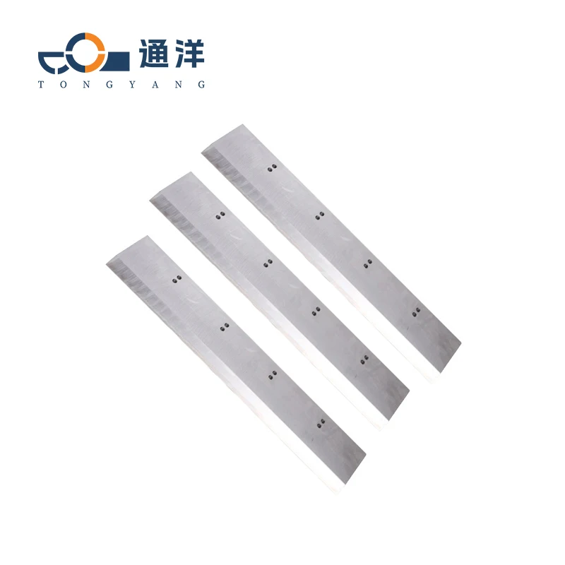
Blade and Cutter Head Installation
Loosen the set screw → Insert the blade fully to the bottom (approx. 13 mm) → Tighten the set screw. Rotate the spindle by hand to confirm no jamming and no eccentricity
Align the guide rivet with the slot and press it in until a **click** is heard to confirm it is fully seated. Check that the up-and-down movement is smooth without jamming.
Disconnect air supply and power before installation; keep cutting edges facing outward and wear gloves.Disassembly of cylinders or cutter heads by non-professionals is prohibited.

 Hot News