 EN
EN

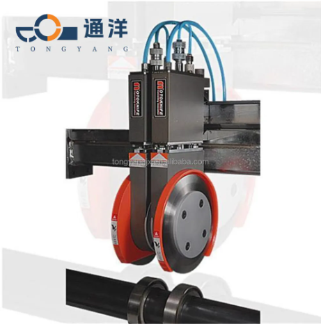
Installing a pneumatic blade holder requires careful attention to detail and proper understanding of compressed air systems. Modern manufacturing facilities increasingly rely on pneumatic blade holder systems for their precision cutting applications, offering superior control and consistency compared to traditional mechanical alternatives. The installation process involves multiple critical steps that must be executed correctly to ensure optimal performance and safety. Understanding the fundamental principles behind pneumatic blade holder operation will help technicians achieve successful installations while maintaining system integrity.
Understanding Pneumatic Blade Holder Components
Essential System Components
A pneumatic blade holder system consists of several interconnected components that work together to provide precise cutting control. The main assembly includes the pneumatic actuator, blade mounting bracket, air supply lines, and pressure regulation components. Each pneumatic blade holder requires a dedicated air compressor capable of delivering consistent pressure within the specified operating range. The actuator mechanism converts compressed air pressure into linear or rotational motion, depending on the specific application requirements.
Control valves play a crucial role in pneumatic blade holder operation by regulating air flow and pressure distribution throughout the system. These valves must be properly sized and configured to match the pneumatic blade holder specifications. Pressure sensors and feedback systems ensure accurate positioning and force control during cutting operations. Understanding these components helps technicians identify potential issues and implement effective troubleshooting strategies.
Air Supply Requirements
Proper air supply configuration is fundamental to successful pneumatic blade holder installation and operation. The compressed air system must provide clean, dry air at consistent pressure levels to prevent contamination and ensure reliable performance. Moisture and particulate contamination can cause premature wear and operational failures in pneumatic blade holder systems. Installing appropriate filtration and air treatment equipment protects sensitive components from damage.
Air pressure requirements vary depending on the specific pneumatic blade holder model and application demands. Most industrial systems operate within a pressure range of 80 to 120 PSI, though some specialized applications may require higher or lower pressures. Pressure regulators must be calibrated accurately to maintain consistent operating conditions throughout the cutting process. Regular monitoring of air quality and pressure levels ensures optimal pneumatic blade holder performance.
Pre-Installation Planning and Safety
Site Preparation Requirements
Thorough site preparation is essential before beginning pneumatic blade holder installation procedures. The installation area must provide adequate space for equipment access, maintenance operations, and safety clearances. Electrical power requirements should be verified and appropriate connections established for any electronic control components. The mounting surface must be level, stable, and capable of supporting the pneumatic blade holder assembly under full operating loads.
Environmental conditions significantly impact pneumatic blade holder performance and longevity. Temperature extremes, humidity levels, and exposure to contaminants must be considered during site selection and preparation. Proper ventilation ensures adequate air circulation around pneumatic components while preventing moisture accumulation. Establishing clear work zones and implementing appropriate safety barriers protects personnel during installation and operation.
Safety Protocols and Procedures
Safety considerations are paramount when working with pneumatic blade holder systems due to the inherent risks associated with compressed air and sharp cutting implements. All personnel involved in installation must receive proper training on pneumatic system safety and emergency procedures. Personal protective equipment including safety glasses, gloves, and appropriate clothing must be worn throughout the installation process. Lockout/tagout procedures should be established and followed when working on energized pneumatic systems.
Compressed air safety requires special attention to prevent injury from high-pressure releases or equipment failures. Pneumatic blade holder systems store significant energy in compressed air reservoirs and actuators. Proper pressure relief procedures must be followed before disconnecting air lines or removing components. Emergency stop systems should be tested and verified operational before commencing normal operations with the pneumatic blade holder.
Mechanical Installation Procedures
Installation and calibration
Precise installation and calibration are crucial for the successful installation of a pneumatic tool holder. The mounting base must be precisely positioned according to manufacturer specifications and application requirements. Use precision measuring instruments to verify alignment tolerances and ensure proper positioning relative to workpiece handling systems. Secure mounting prevents vibration and movement that could affect cutting accuracy and blade life.
Alignment procedures for pneumatic blade holder systems require careful attention to both horizontal and vertical positioning. The trajectory of the blade must be verified to ensure it maintains clearance with surrounding equipment and engages correctly with the workpiece. The installation accuracy of the pneumatic tool holder affects cutting quality, blade wear, and the overall performance of the system. Regular alignment checks should be scheduled as part of routine maintenance procedures.
Mechanical Connections
Proper mechanical connections ensure reliable operation and prevent component failure during pneumatic blade holder operation. All bolted connections must be torqued to manufacturer specifications using calibrated tools. Thread-locking compounds may be required for critical connections subject to vibration or thermal cycling. Coupling alignments between pneumatic actuators and blade assemblies require precise adjustment to prevent binding or excessive wear.
Flexible couplings accommodate minor misalignments while transmitting motion from pneumatic actuators to blade mechanisms. These couplings must be properly sized and installed according to manufacturer guidelines. Regular inspection of mechanical connections identifies loose fasteners or wear before failures occur. Proper lubrication of moving components extends service life and maintains smooth operation throughout the pneumatic blade holder system.
Pneumatic System Installation
Air Line Routing and Connections
Systematic air line routing ensures reliable pneumatic blade holder operation while maintaining system efficiency. Air supply lines must be sized appropriately to handle flow requirements without excessive pressure drop. Routing paths should minimize the number of fittings and avoid sharp bends that restrict airflow. Support brackets and clamps secure air lines and prevent stress on connections during system operation.
Connection fittings for pneumatic blade holder systems require proper selection based on pressure ratings and environmental conditions. Push-to-connect fittings offer convenience for maintenance while threaded connections provide maximum security for high-pressure applications. Before putting the pneumatic tool holder into use, all connections must be tested for gas leaks using appropriate testing methods.Gas-tight connections ensure efficient operation of the cutting system and prevent contaminants from entering.
Pressure Regulation and Control
Accurate pressure regulation is fundamental to consistent pneumatic blade holder performance across varying operating conditions. Primary pressure regulators reduce supply pressure to working levels while maintaining stable output despite input variations. Secondary regulators may be required for systems with multiple pneumatic blade holder units or different pressure requirements. Pressure gauges provide visual indication of system operating conditions.
Control valve installation determines the responsiveness and precision of pneumatic blade holder operation. Directional control valves manage air flow to extend and retract pneumatic actuators according to control signals. Flow control valves adjust actuator speed for specific application requirements. Proper valve sizing and configuration optimize pneumatic blade holder performance while minimizing air consumption and operating costs.
Electrical and Control System Integration
Control Interface Connections
Modern pneumatic blade holder systems often incorporate electronic controls for enhanced precision and automation capabilities. Control interface connections must be made according to electrical codes and manufacturer specifications. Proper grounding prevents electrical noise interference while surge protection devices guard against voltage transients. Cable routing should maintain separation between power and control circuits to prevent electromagnetic interference.
Sensor connections provide feedback for position monitoring and force control in advanced pneumatic blade holder applications. These sensors require careful calibration and protection from environmental contaminants. Signal conditioning may be necessary to interface sensors with control systems. Proper shielding and grounding of sensor cables ensures reliable signal transmission and prevents false readings that could affect pneumatic blade holder operation.
Programming and Configuration
Control system programming enables customization of pneumatic blade holder operation for specific application requirements. Parameters such as cutting speed, force limits, and position accuracy can be adjusted through software interfaces. Programming should include safety interlocks and emergency stop functions to protect personnel and equipment. Regular backup of control programs prevents loss of configuration data and facilitates system recovery.
Human-machine interface configuration allows operators to monitor and control pneumatic blade holder systems effectively. Display screens provide real-time status information and alarm notifications. Operator controls must be intuitive and positioned for safe and efficient operation. Training programs ensure operators understand proper procedures for pneumatic blade holder operation and emergency response.
Testing and Commissioning
System Function Testing
Comprehensive function testing verifies proper pneumatic blade holder installation and identifies any issues before placing the system into production service. Initial testing should begin with low-pressure operations to check basic functionality and detect potential problems safely. All safety systems must be tested and verified operational before proceeding with full-pressure testing. Documentation of test results provides baseline performance data for future reference.
Performance testing evaluates pneumatic blade holder accuracy, repeatability, and speed under various operating conditions. Test cuts on representative materials verify cutting quality and dimensional accuracy. Cycle time measurements determine production capability and identify potential bottlenecks. Load testing confirms the pneumatic blade holder can handle maximum specified forces without degradation in performance or safety.
Calibration and Adjustment
Precise calibration ensures the pneumatic blade holder operates within specified tolerances and meets application requirements. Position sensors require calibration to provide accurate feedback for closed-loop control systems. Force calibration verifies that cutting pressures remain within safe limits while achieving required penetration. Regular calibration schedules maintain accuracy over time and compensate for normal wear and aging.
Fine-tuning adjustments optimize pneumatic blade holder performance for specific materials and cutting requirements. Speed adjustments balance productivity with cut quality and blade life. Force adjustments prevent excessive loading while ensuring complete material penetration. These adjustments may require iterative testing to achieve optimal results for each specific application the pneumatic blade holder will encounter.
Maintenance and Troubleshooting
Preventive Maintenance Procedures
Regular preventive maintenance ensures reliable pneumatic blade holder operation and extends component service life. Daily inspections should include visual checks of air lines, fittings, and mechanical components for signs of wear or damage. Air filter elements require regular replacement to maintain clean air supply to pneumatic components. Lubrication schedules must be followed to prevent premature wear of moving parts within the pneumatic blade holder assembly.
Scheduled maintenance intervals depend on operating conditions and usage intensity of the pneumatic blade holder system. High-duty cycle applications may require more frequent maintenance than intermittent operations. Maintenance records track component replacement history and help predict future service requirements. Proactive maintenance prevents unexpected failures and minimizes production downtime associated with pneumatic blade holder repairs.
Common Issues and Solutions
Troubleshooting pneumatic blade holder problems requires systematic diagnosis to identify root causes and implement effective solutions. Pressure-related issues often stem from air supply problems, worn seals, or contaminated valves. Mechanical problems may result from misalignment, excessive wear, or improper lubrication. Understanding common failure modes helps technicians quickly restore pneumatic blade holder operation.
Performance degradation in pneumatic blade holder systems typically develops gradually as components wear or operating conditions change. Regular monitoring of key parameters helps identify trends before failures occur. Replacement part availability and proper inventory management ensure quick restoration of service when maintenance is required. Training programs keep maintenance personnel updated on proper pneumatic blade holder service procedures.
FAQ
What air pressure is required for pneumatic blade holder operation
Most pneumatic blade holder systems operate effectively within a pressure range of 80 to 120 PSI, though specific requirements vary by manufacturer and application. The air supply must provide consistent pressure without significant fluctuations to ensure reliable cutting performance. Higher pressures may be required for heavy-duty applications or when cutting thick materials, while lower pressures suffice for lighter cutting tasks.
How often should pneumatic blade holder systems be maintained
Maintenance frequency for pneumatic blade holder systems depends on operating conditions and usage intensity. Daily visual inspections help identify potential issues early, while weekly lubrication and monthly filter changes maintain optimal performance. Annual comprehensive inspections should include calibration checks and replacement of wear components to ensure continued reliability and accuracy.
What safety precautions are necessary when installing pneumatic blade holders
Safety precautions for pneumatic blade holder installation include proper lockout/tagout procedures, personal protective equipment, and compressed air safety protocols. All personnel must be trained on emergency procedures and proper handling of pneumatic components. Work areas should be properly ventilated and equipped with emergency stop systems accessible to all operators working near the pneumatic blade holder.
Can pneumatic blade holders be automated with existing control systems
Modern pneumatic blade holder systems can be integrated with most industrial control systems through standard interfaces and communication protocols. Automation capabilities include position control, force monitoring, and cycle time optimization. Integration requires proper sensor selection, control programming, and interface hardware to ensure reliable communication between the pneumatic blade holder and existing automation systems.